By Jenny Mills · rural nurse & homesteader · health, safety, law and the paperwork of going bush
“After a bushfire scare in 2019, I learned that 35mm² copper bus bars are the only thing stopping a $15,000 inverter from melting down in a heatwave.”
By Jenny Mills · rural nurse & homesteader · health, safety, law and the paperwork of going bush
“After a bushfire scare in 2019, I learned that 35mm² copper bus bars are the only thing stopping a $15,000 inverter from melting down in a heatwave.”
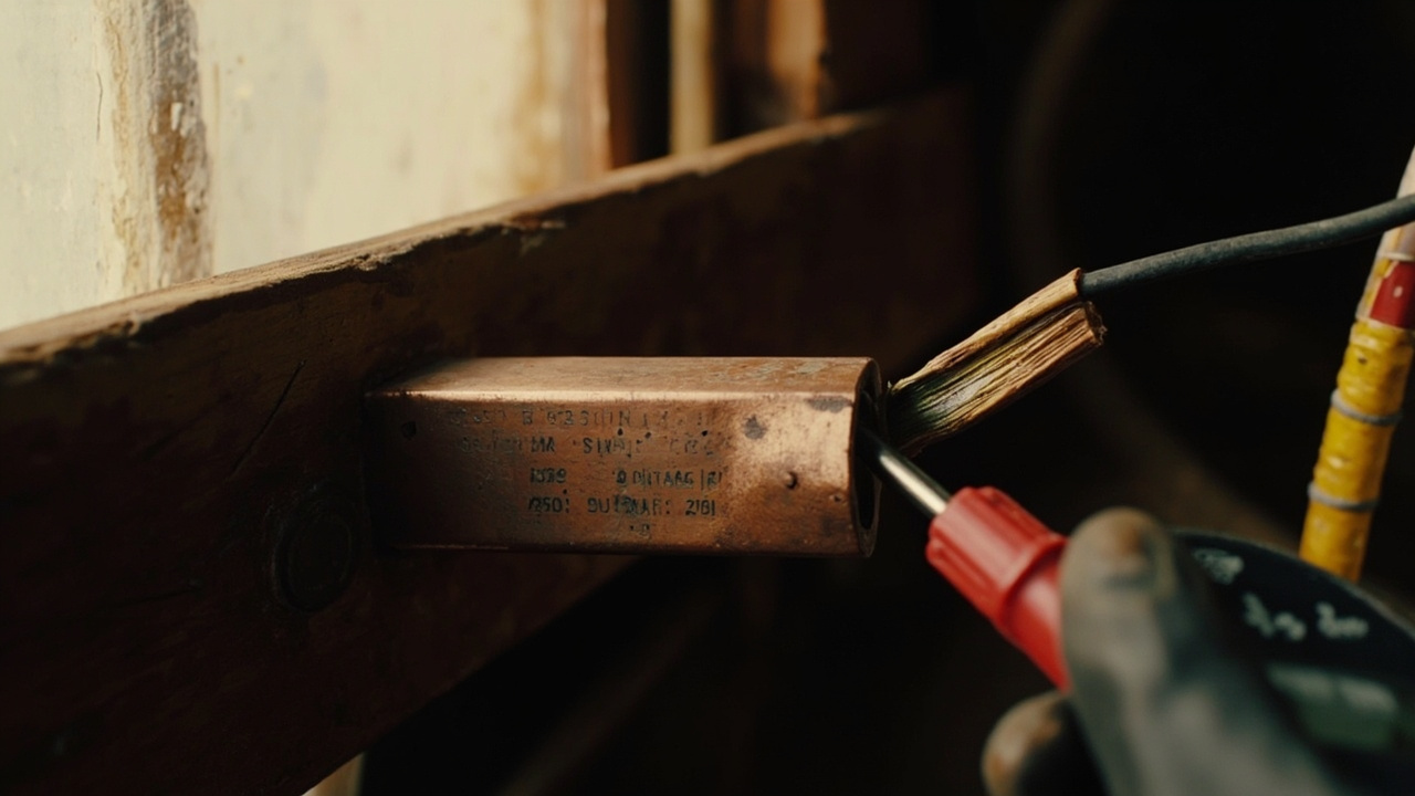
A busbar is a heavy metallic conductor that collects and distributes current inside low-voltage switchgear, distribution boards and industrial power panels. In an off-grid system, it is typically the central connection point between major current sources, protection equipment and loads.
The important point is that busbar selection is not simply a case of matching a bar to the inverter’s maximum current. Heat, material, enclosure, connections and the required temperature rise all matter.
This guide covers busbar selection for both AC (230 V, 50 Hz) distribution equipment and DC (typically 12/24/48 V) battery and inverter interconnects in an Australian off-grid installation. AC switchboard busbars and DC battery/inverter busbars have different ampacity, termination and fault behaviour, and are addressed separately below. It is general engineering information, not a substitute for a design verified for the particular equipment and installation.
| Requirement | What to check | Why it matters |
|---|---|---|
| Material | Copper or aluminium | Conductivity, physical size and thermal expansion differ. |
| Current path | Maximum expected current and the connected protection arrangement | The bar must carry the required current without excessive temperature rise. |
| Cross-sectional area | Adequate for the material and installation conditions | A larger area reduces resistance and heat generated by current flow. |
| Surface finish | Clean, sound and suitable for the connection method | Surface condition can affect heat dissipation and contact behaviour. |
| Mounting orientation | Vertical, horizontal or other supported arrangement | Orientation affects current-carrying capacity and temperature rise. |
| Enclosure ventilation | Open, ventilated or confined installation | Heat dissipation is reduced when airflow is restricted. |
| Allowable temperature rise | Relevant design and standard requirements | Temperature rise, rather than peak current alone, can determine the acceptable design. |
| Connections | Correctly rated, clean and secure terminals | Loose or poor connections increase resistance and heat. |
| Protection | Suitable overcurrent and short-circuit protection | The busbar and connected conductors must be protected against fault current. |
| Corrosion exposure | Indoor, humid, coastal or other harsh environment | Connection protection and material finish need consideration. |
| Long runs | Thermal movement, especially with aluminium | Expansion may need to be accommodated over long busbar runs. |
Copper and aluminium are both used for busbars, but they are not interchangeable in a design.
Copper has higher electrical conductivity: approximately 58 MS/m, compared with approximately 35 MS/m for aluminium. Aluminium therefore generally needs a cross-sectional area around 1.5–1.6 times greater than copper to carry the same current under comparable conditions.
That does not mean copper is automatically the correct choice for every installation. Material selection also needs to consider the available space, connection system, mechanical support, corrosion protection, expansion and the rest of the installation design.
Copper is the common choice where a compact conductor is wanted and where the design uses compatible copper connections. Its higher conductivity means less cross-sectional area may be required than for aluminium carrying the same current.
For humid or coastal installations, tinned copper is a sound engineering option where appropriate to the connection design. The tin finish can provide an additional corrosion-resistant surface, but the complete system still depends on correct sealing, protection and maintenance.
Aluminium is also suitable for busbar applications, but its lower conductivity means a larger cross-sectional area is generally required. It also has a higher thermal expansion coefficient than copper: 23 μm/m·K for aluminium versus 17 μm/m·K for copper.
Long aluminium runs may therefore require expansion joints or other provision for thermal movement. Aluminium connections also need careful attention to joint design, surface preparation, corrosion protection and mechanical security. Both copper and aluminium can corrode depending on environment; bimetallic connections require appropriate plating, treatment or compatible barrier materials to prevent galvanic attack.
Heat generated in a conductor follows I²R. That relationship matters because the heat rises rapidly as current increases. A conductor that appears adequate at normal current can still overheat at a higher load, during a fault, or when its ability to dissipate heat is reduced.
A useful design principle is to include safety margin, or headroom, above the maximum expected current. However, there is no verified universal ampacity figure that can be applied to every busbar.
Manufacturer data sheets for the specific bar profile, material and termination typically publish a typical range of 1.4–1.8 A/mm² for flat busbar in free air at a 35 °C ambient temperature and a 70 K temperature rise. That is a stated range for those conditions, not a generic rating for every busbar size, enclosure, material or installation.
The following conditions can all change the result:
The allowable temperature rise is the binding constraint in busbar sizing, rather than peak current alone. This is why a copied ampacity table should not be treated as a complete design.
Before selecting a busbar, identify every source and load that may feed or draw current through it.
For an off-grid system, that can include some or all of the following:
The maximum expected current must be established for the specific arrangement. A busbar connected to a single inverter is not necessarily exposed to the same current as a busbar shared by multiple parallel sources or loads.
Do not size the busbar from the inverter nameplate alone. The current path, connection arrangement, protection coordination and expected operating conditions all form part of the calculation.
AC switchboard busbars (typically 230 V, 50 Hz in Australia) and DC battery/inverter busbars (commonly 12, 24 or 48 V) are sized and built differently:
Decide which busbar you are sizing before applying any table.
The correct approach is to treat the busbar as part of a thermal system, not as a solid piece of metal with a single universal rating.
Start by selecting the material and determining the cross-sectional area needed for the intended current and installation conditions. The higher conductivity of copper means that copper can generally use less area than aluminium for the same current.
The required area must not be selected from a generic current figure alone. Compare the proposed arrangement with the stated conditions of any available ampacity data and adjust the design where the actual installation differs.
The surface finish affects current-carrying capacity and temperature rise. It also affects the quality and reliability of the connection.
Surfaces at connection points should be clean, flat and free from damage, contamination and corrosion that could impair the contact. The connection method and the manufacturer’s preparation requirements take priority.
A busbar in free air can dissipate heat differently from the same bar mounted inside a sealed or poorly ventilated enclosure.
Check:
A bar that is technically adequate in open air may be undersized inside a hot, tightly packed distribution board.
Temperature rise is the design limit that matters. Excessive temperature can cause:
The result is not merely a warmer busbar. Repeated overheating can progressively damage the installation and create a serious fault risk.
A busbar is only as good as its connections and support arrangement.
The terminals, lugs, fasteners and connecting conductors must be compatible with the busbar material and the current path. Do not assume that a mechanical fit is sufficient.
The contact surfaces and fasteners should be installed according to the equipment and connection manufacturer’s instructions. A connection that is dirty, distorted, under-tightened, over-tightened or mismatched can increase resistance and heat.
Dielectric grease is an insulator. It must not be applied between mating conductive contact surfaces, where it will raise contact resistance and cause heating.
Use dielectric grease only where it is appropriate: on insulator surfaces, on threaded fasteners and hardware, and as a sealant around an already-made connection to exclude moisture. Where a contact aid or corrosion inhibitor is needed on the conductive mating faces themselves, use a product rated for that purpose (for example No-Ox-ID, Kopr-Shield or an equivalent contact-rated compound) and follow the busbar, lug and termination manufacturer’s instructions.
Secure mechanical mounting is important. Busbars and their conductors should be supported so that movement, vibration and cable strain do not progressively loosen the connection.
A loose connection can increase resistance and generate additional heat. Mechanical security is therefore part of the electrical design, not just an installation finish.
The busbar and its connected conductors must be protected against overcurrent and short-circuit current using appropriately rated protection equipment. The protection arrangement must be coordinated with the conductors, devices and fault levels of the actual system.
Protection does not make an undersized busbar safe. It is a safeguard, not a substitute for correct thermal design.
Moisture and contamination can attack busbar surfaces and connection points. In coastal or humid locations, consider:
Tinned copper is a sound engineering choice for corrosion resistance in coastal or humid environments when it suits the complete design.
Aluminium expands more than copper for a given temperature change. The published linear expansion coefficients are 23 μm/m·K for aluminium and 17 μm/m·K for copper.
For long aluminium busbar runs, assess the need for expansion joints or other means of accommodating movement. A rigidly restrained long run can develop mechanical stress as temperature changes, even when the electrical current is within the intended range.
Busbar sizing in Australia draws on several documents, depending on whether the bar is part of an AC switchboard assembly or a DC battery/inverter interconnect:
For an Australian installation, record the design basis. Documentation should identify at least:
Do not present a copied generic ampacity figure as a final rating. The commonly quoted 1.4–1.8 A/mm² range applies to flat busbar in free air at 35 °C ambient and a 70 K temperature rise. Other arrangements require separate assessment against manufacturer data and the applicable standard.
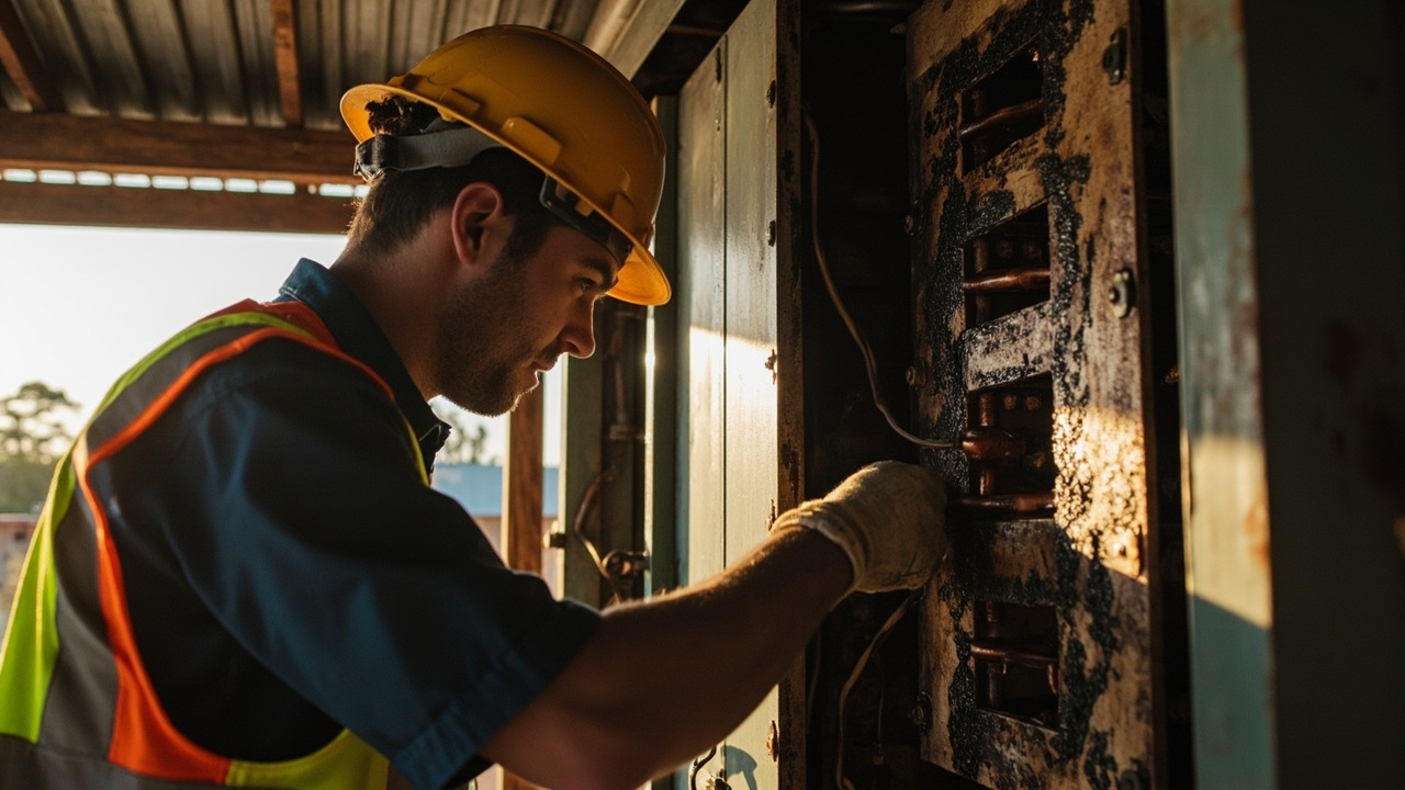
Busbars can be exposed to lethal current, high fault energy and enough heat to start a fire. Incorrect sizing, loose connections, contamination or an unsuitable enclosure can turn a small installation problem into a major hazard.
Before working on a busbar assembly:
1. Isolate all sources of supply, including batteries, inverter, generator, solar charge equipment and any grid or auxiliary input.
2. Verify that the system is de-energised using an appropriate test procedure.
3. Do not rely on switching off a control panel alone; battery-connected equipment may remain energised.
4. Protect the work area against accidental re-energisation.
5. Follow the equipment manufacturer’s isolation, test and restart procedures.
6. Inspect the enclosure, insulation, terminals, fasteners and conductors after any work.
In Australia, fixed wiring work and DC battery installations above extra-low voltage must be performed or verified by a licensed electrician in accordance with AS/NZS 3000 and the relevant state or territory electrical safety regulations. The following situations in particular require a licensed electrical professional:
A licensed professional should verify the final arrangement against the applicable Australian requirements and the manufacturer’s instructions.
No. Copper has higher conductivity and generally needs less cross-sectional area for the same current, but aluminium is also a valid busbar material when the design accounts for its lower conductivity, larger cross-section, higher thermal expansion and the connection system used. Material selection depends on the installation: available space, weight, cost, corrosion environment, termination hardware and the relevant standard. Neither metal is universally better; both require correct sizing, termination and protection for the specific job.
Worth a watch: Our Bus is Going Off Grid: Connecting Solar Panels and Running Wires · Di and Sam (Tiny Aussie Homestead)