Interact with the 3D model above. Use AR mode on mobile devices for an immersive site overlay, or refer to Engineering Drawings for precision.
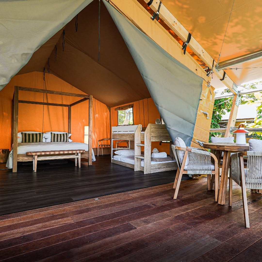
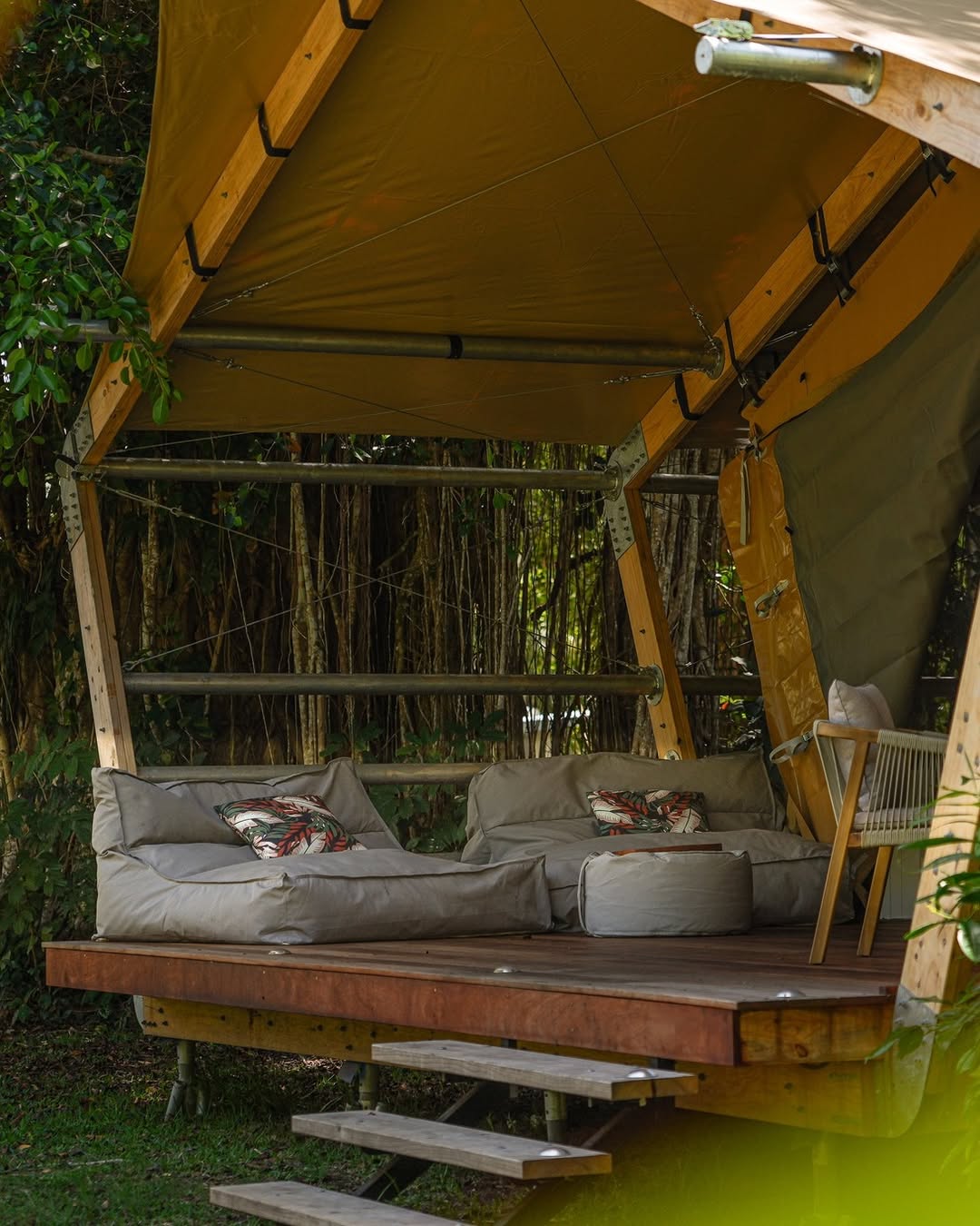
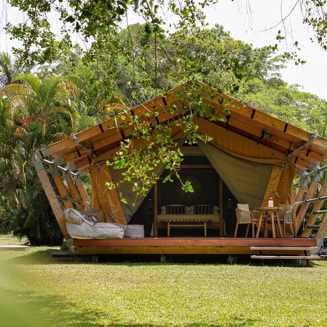
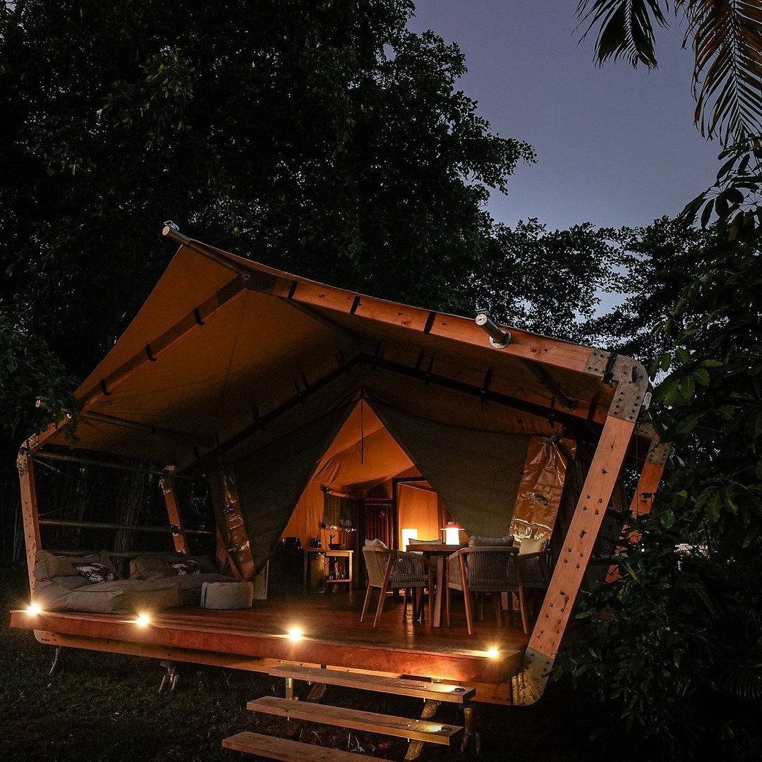
Reference Implementation: Daintree Project
Completed installation example using the standard cyclonic frame. Note the anchor spacing and finished tensioning.
Connection Detail
Completed Frame
Site Context
Roof Line
Technical Drawings: Tube & Connector Details
⚠️ CRITICAL WARNING: TUBE SIZES ARE NOT IDENTICAL!
Even though they look the same, there is a 10mm (1cm) difference for the outer pipes.
P3 is the shorter one (2420mm) vs 2430mm. Do not mix them up!
Reference snapshots for P1–P7 tube lengths, cap plates, hole alignment, and connector assemblies.
Frame overview
Elevation bracing spans
Tube length overview (P1–P7)
P1 tube detail
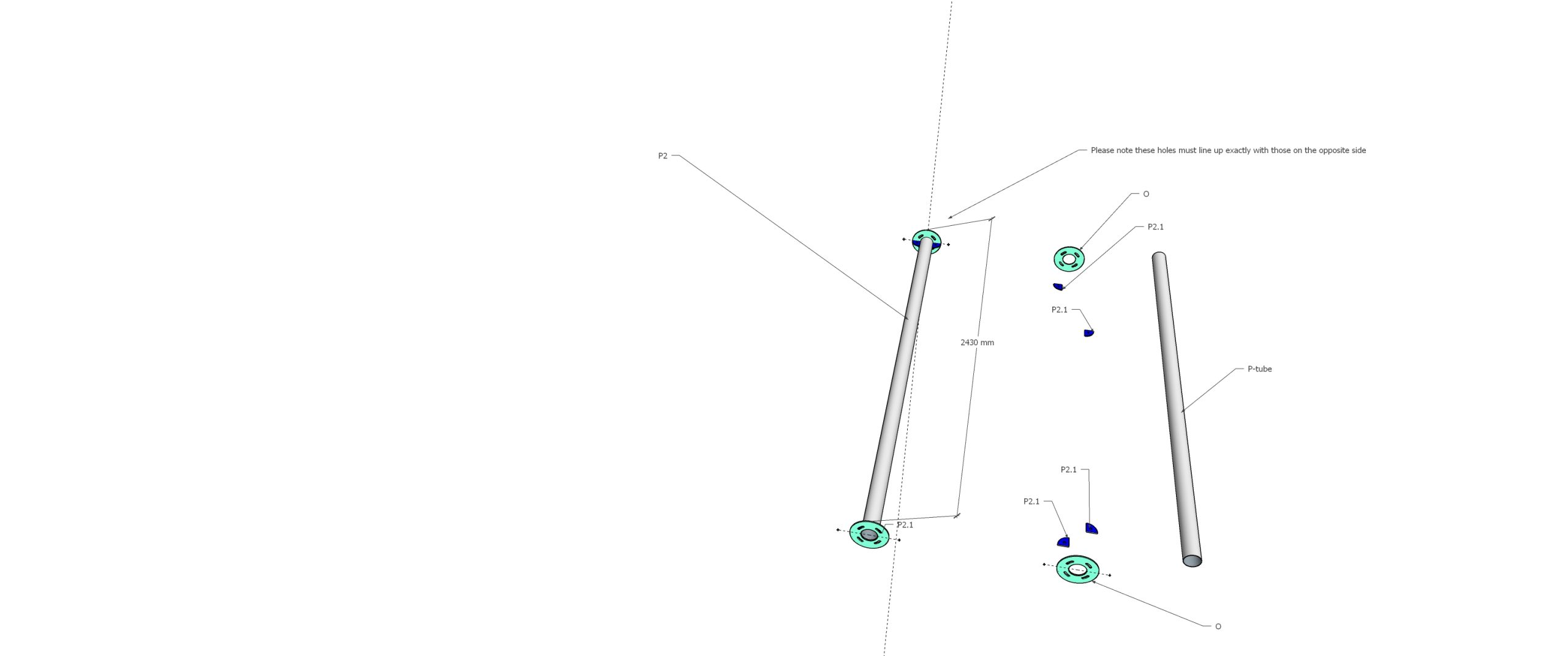
P2 tube detail
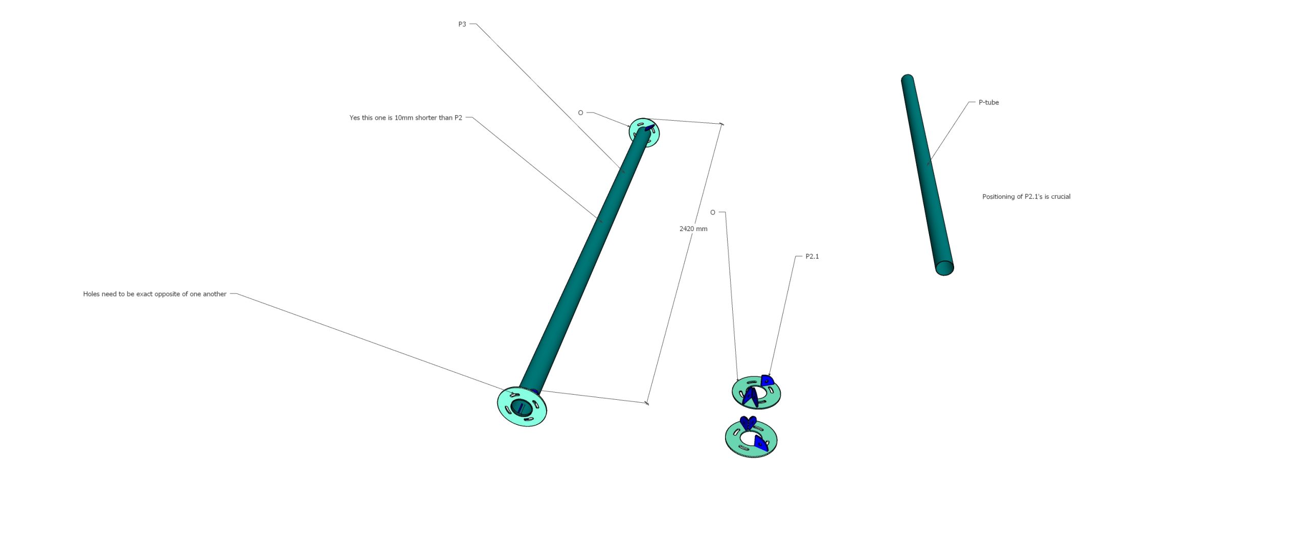
P3 tube detail (2420mm - Shorter!)
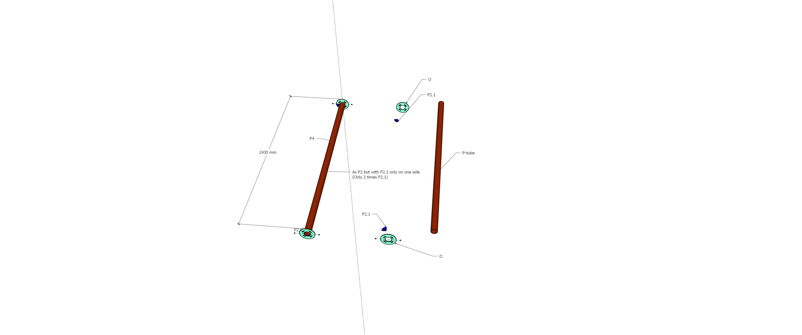
P4 tube detail
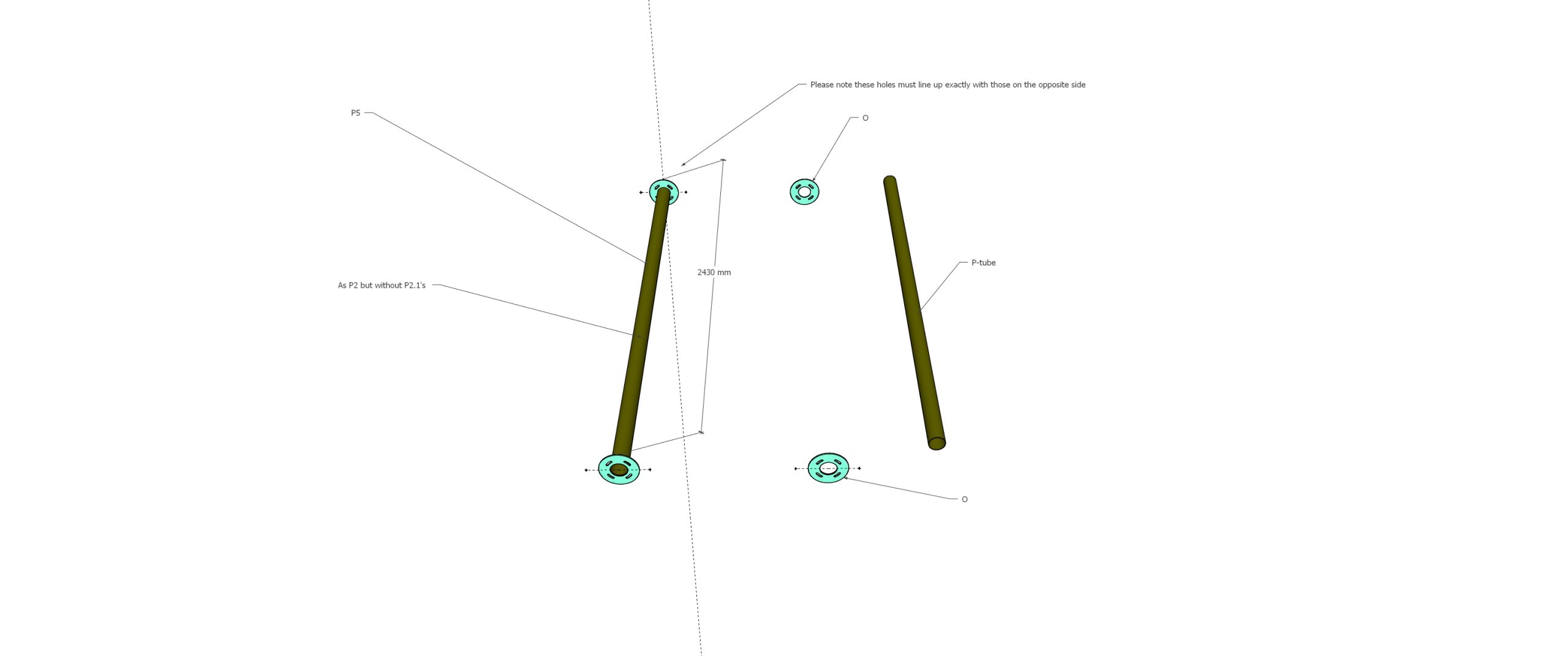
P5 tube detail
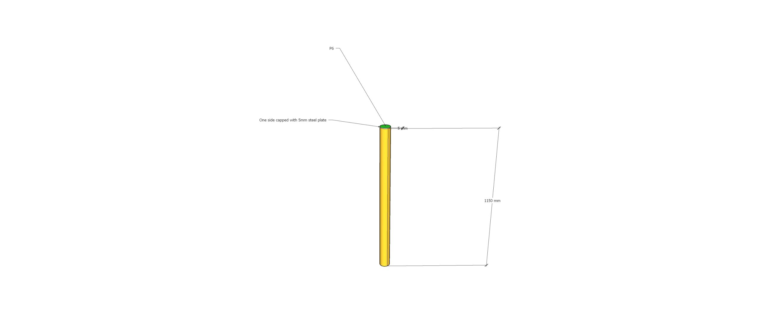
P6 tube detail
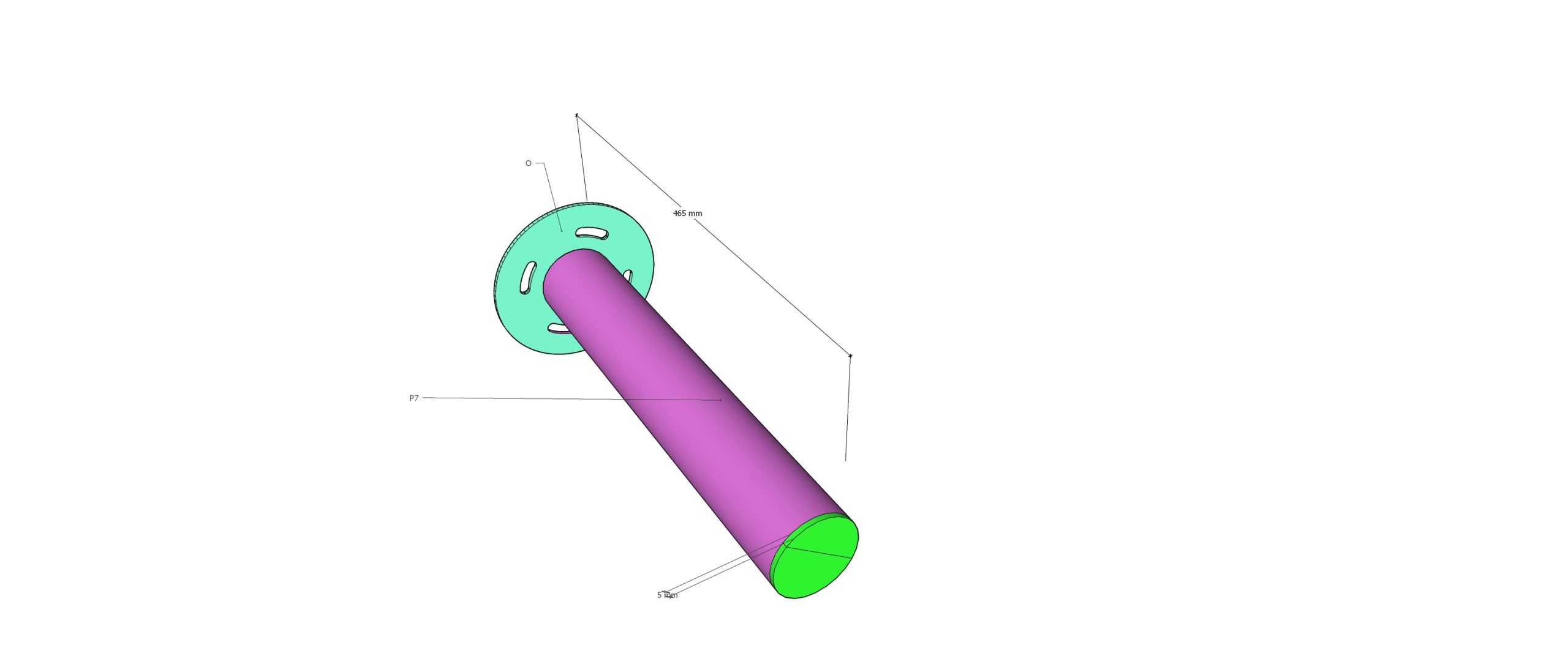
P7 cap plate detail
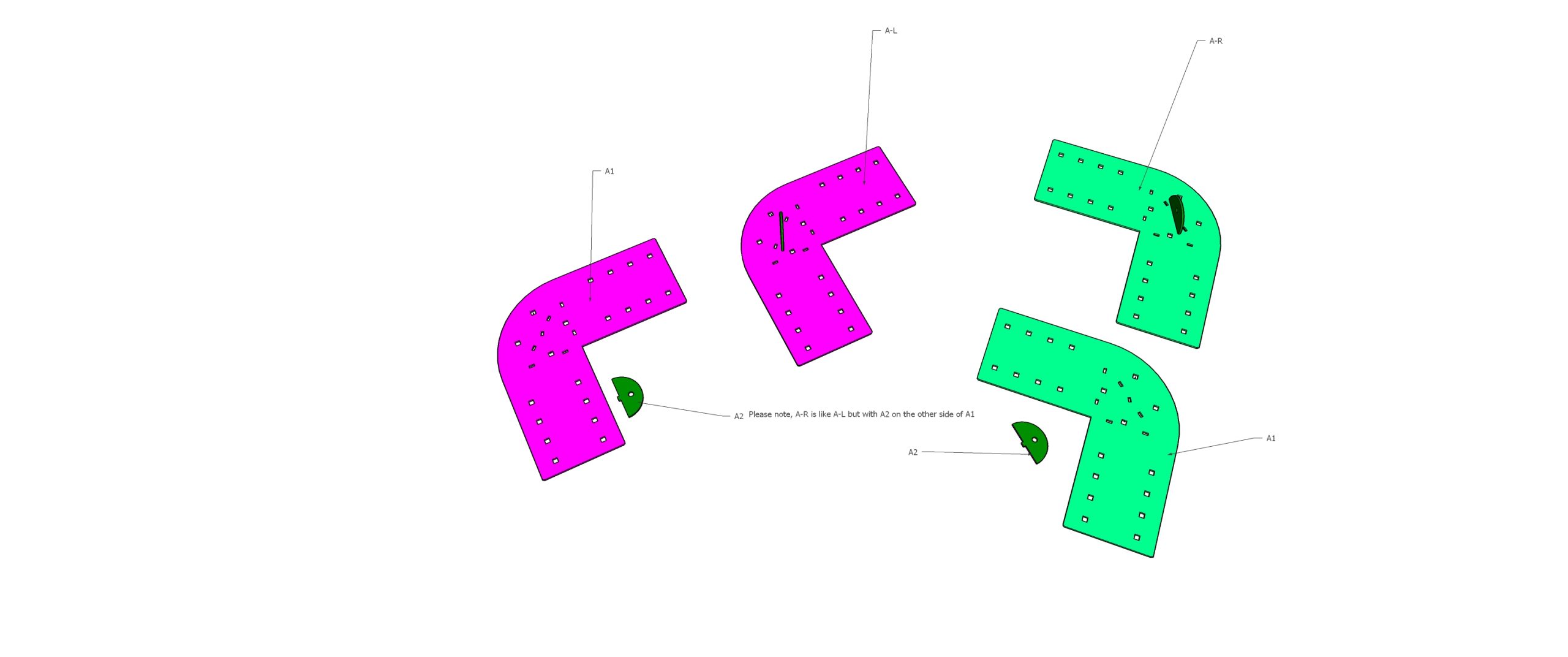
A1 / A-left / A-right with A2
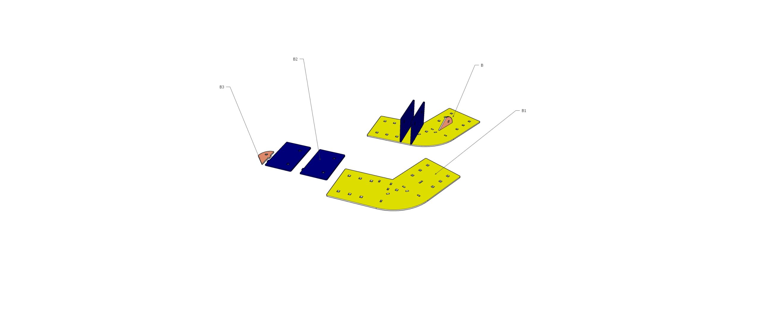
B assembly components
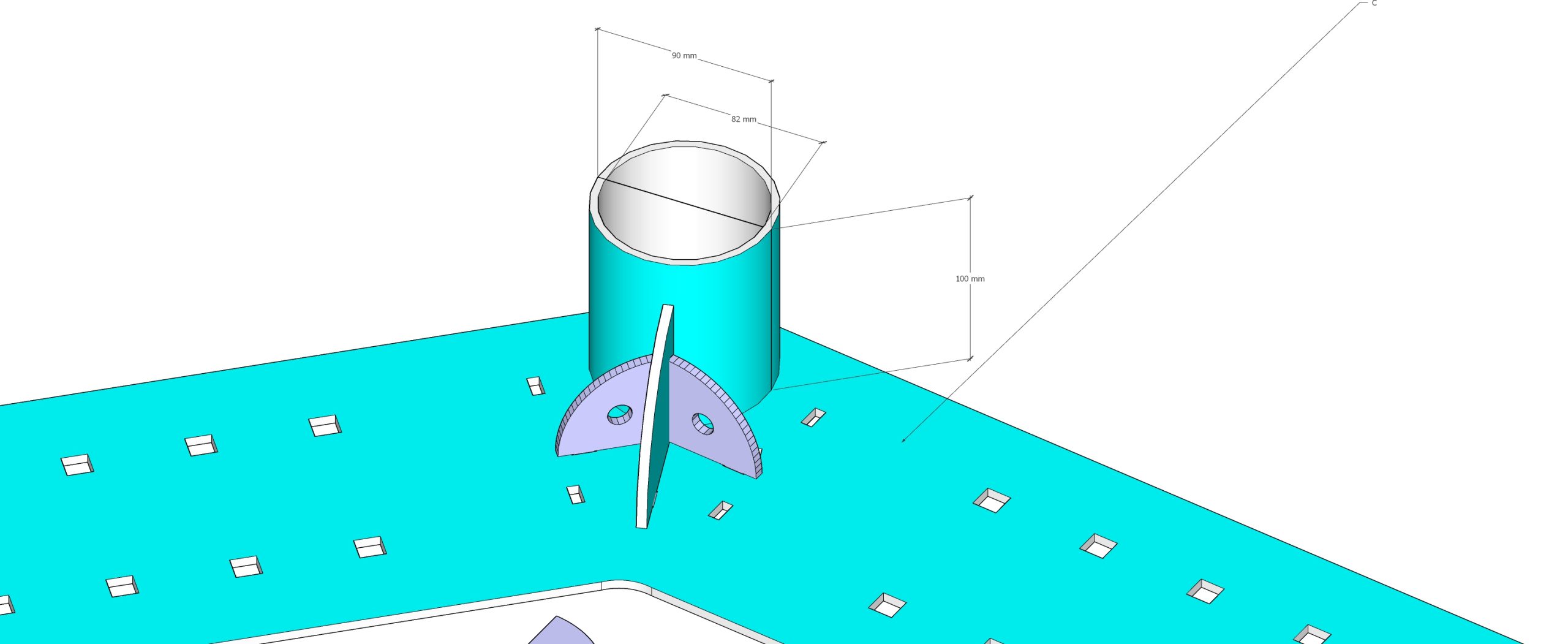
Part C tube and gussets
1. Project Analysis: Gionfriddo Review
What Went Wrong
Critical Issues Identified:
- Material Shortages: Extra straps were required mid-project.
- Product Defects: "Unsatisfactory product" reports citing faulty brackets, inconsistent spacing, and "ideal corner" mismatches.
- Manufacturing Flaws: Warping in long line welds (Part B) and welding contamination in adjacent holes.
- Manual Gaps: Confusion regarding installation steps, necessitating multiple manual revisions and clarifications.
Corrections for P7 & Manufacturing
Implemented Solutions:
- P7 & P6 Cap Plates: Now require FSBW (Full Strength Butt Welded) - full penetration weld all around.
- Tube Compatibility: P7 and P6 steel tubes must be verified to fit inside Part C tubes before shipping.
- Welding Scope: Confirmed welding for all drawings P1-P7; steel tube attached to Part C.
- Part D: Identified as a universal spacer (no welding required).
Manual Updates Required
- Step 0 Clarity: Emphasize "Familiarize with C3920" and the 3D model before starting.
- Visual Aids: Use AR overlay (Sketchfab) for quick visual set-out and "Step 0" familiarization.
- Anchor Specifics: Explicit instructions for double-stacked storm anchors at max 60 degrees.
2. Technical Documentation
Bill of Materials (BOM) - Per Tent Quantity
Status Update: This list has been updated to include the corrected P7 connector quantities (4 per tent) which were previously missing from initial shipments.
Supplier: Tianjin Emerson Commercial and Trade Co., Ltd.
| Item Description |
Spec (Weight/pc) |
Qty Per Tent |
Total Weight (Per Tent) |
| A-left | 6.3 kg | 2 | 12.6 kg |
| A-right | 6.3 kg | 2 | 12.6 kg |
| A1 | 6.1 kg | 12 | 73.2 kg |
| B-left | 6.9 kg | 6 | 41.4 kg |
| B-right | 6.9 kg | 6 | 41.4 kg |
| B1 | 4.6 kg | 4 | 18.4 kg |
| C | 6.9 kg | 8 | 55.2 kg |
| D (Spacer) | 1.3 kg | 60 | 78.0 kg |
| P1 | 20.45 kg | 3 | 61.35 kg |
| P2 | 22.5 kg | 10 | 225.0 kg |
| P3 | 22.45 kg | 6 | 134.7 kg |
| P4 | 22.5 kg | 2 | 45.0 kg |
| P5 | 22.5 kg | 4 | 90.0 kg |
| P6 | 22.5 kg | 2 | 45.0 kg |
| P7 | 5 kg | 4 | 20.0 kg |
Note: Quantities derived from the "5 Tent Quantity List" (15/01/2026).
Darwin Project Specifics - Adjusted Quantity List (3 Tents)
Total Project Requirement: 3 Units
Steel Connectors (BOM)
| Item | Qty (3 Tents) |
|---|
| A-left | 6 |
| A-right | 6 |
| A1 | 36 |
| B-left | 18 |
| B-right | 18 |
| B1 | 12 |
| C | 24 |
| D | 180 |
| P1 | 9 |
| P2 | 30 |
| P3 | 18 |
| P4 | 6 |
| P5 | 12 |
| P6 | 6 |
| P7 | 12 |
Cabling & Bracing
| Component | Qty (3 Tents) |
|---|
| Storm Cables | 36 |
| Turnbuckles | 36 |
| Wire Rope Grips | 144 |
| Thimbles | 72 |
| Mega Anchors | 72 |
| Straps | 12-24 |
Additional Installation Components (Cabling & Bracing)
Note: The following items are required for structural integrity (cyclonic rating) but were not supplied in the steel connector package. These must be sourced separately. Reference images: S234_thimble_web.jpg and 2023-06-14_8-06-17.jpg.
| Component |
Specification/Notes |
Qty Per Tent |
Application |
| Storm Cables | Galvanized Steel Wire Rope (10mm recommended, 7x19 strand). Length varies by anchor distance (est. 6m per cable). | 12 assemblies | External hold-down (Calculated as 12 points per tent). |
| Turnbuckles | Heavy Duty Galvanized M16 (Hook/Eye or Eye/Eye). Working Load Limit >1.5T. | 12 | Tensioning storm cables. |
| Wire Rope Grips/Clamps | Galvanized (Double saddle preferred for cyclonic) to suit 10mm wire. | 48 (4 per cable) | Securing cable loops/thimbles (2 per loop end). |
| Thimbles | Galvanized steel (S234 Standard) to suit 10mm wire. | 24 (2 per cable) | Protecting cable eyes at attachment points. |
| Mega Anchors | Double-stacked configuration required | 24 | Main ground anchorage. Installed at 60° angle. |
| Cross Bracing | Steel cable with tensioners (Optional/Future retrofit) | TBD | Internal frame stability (referenced in project notes). |
| Straps | Heavy duty ratchet/webbing straps | 4-8 (recommended) | Temporary bracing during assembly & cover tensioning. |
Manufacturing Specifications
- Process: CNC Cutting -> Welding (FSBW for caps) -> Hot Dipped Galvanization -> Painting (P1-P7).
- Tolerance: Slots designed to facilitate precise alignment during welding.
- Verification: P1/P6 tube fitment into Part C must be physically tested.
3. Installation Guide
Prerequisites & Site Requirements
- Termite Protection: Structure must be minimum 400mm off the ground on Mega Anchors.
- Tools: Supports (min 130mm high), Digging tools, Mobile device (Apple Pro preferred for AR).
- Safety: Storm cable angles must not exceed 60 degrees.
Step-by-Step Instructions
- Preparation: Lay out all frames matching the 3D Model above. Read all annotations.
- Spacers: Insert D plates (spacers) and use additional bolt holes to clamp plates together before positioning.
- Anchor Set-out: Use the AR overlay for a quick visual guide, then verify exact positions with the Engineering Drawings (C3920).
- Anchor Installation:
- Install double-stacked anchors for storm cables.
- Dig in up to the eyelets.
- Ensure angle is 60 degrees max from attachment location.
- Frame Assembly: Assemble plates B1, B2, B3, C, and D as per Page 5 of the manual.
- Final Check: Verify measurements against Page 7 and 8 of the manual.
Important Note on Measurements: The interactive measurement tool is no longer active. Please refer strictly to the dimensions provided in the PDF manuals and engineering drawings below.
Troubleshooting: If holes don't align, check for welding contamination or warping. Use supports to level frames during assembly.
4. Resource References & Downloads
Key Documentation (Downloads)
Digital Assets & Tools
Use the Sketchfab viewer above for:
- AR Overlay: View the frame in Augmented Reality on supported mobile devices (Modern visualization).
- Visual Reference: Rotate and zoom to understand connection points and frame assembly.
Note: Use downloadable Engineering Drawings for all precise measurements.
5. Project Management
- Timeline: Project communications active 2021-2026. Major installation/correction phase early 2024.
- Key Stakeholders:
- Client: Marco Gionfriddo (Saltwater Properties)
- Project Lead: Daniel (GlamXperience)
- Logistics/Install: Leon Juffermans
- Supplier: Sai / Joyce (Emerson Steel)
- Quality Control:
- Pre-shipment photo verification (welding & galvanization).
- Physical fitment tests for tubes.
- On-site AR verification.